
At Tramex we design quality tools for professionals for use in specialized applications. We believe training is mandatory for using the correct tool to do a great job and we support a large number of excellent training schools around the country to ensure our customers get the most out of our products.
The Dec Scanner is by far the simplest device to use for moisture testing and leak detection of a flat roof, however even a small amount of training can help new users to avoid simple pitfalls.
We will lay out, in these pages, some of the key steps to enable the user to get the best out of this powerful instrument, including setting up and calibrating to a roofing system, developing a methodical approach to inspection and recognising false positives.
Controls
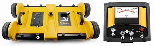
1. Infrared window.
2. ON/OFF – base unit.
3. Battery Compartment.
4. Screw fastener for electrode mat.
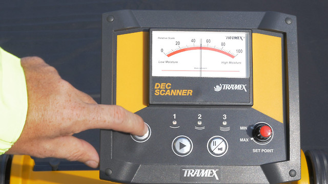
5. ON/OFF – control panel.
6. Range button.
7. LED range indicators.
8. HOLD function / AUDIO signal.
9. SET POINT calibration knob
Assembly
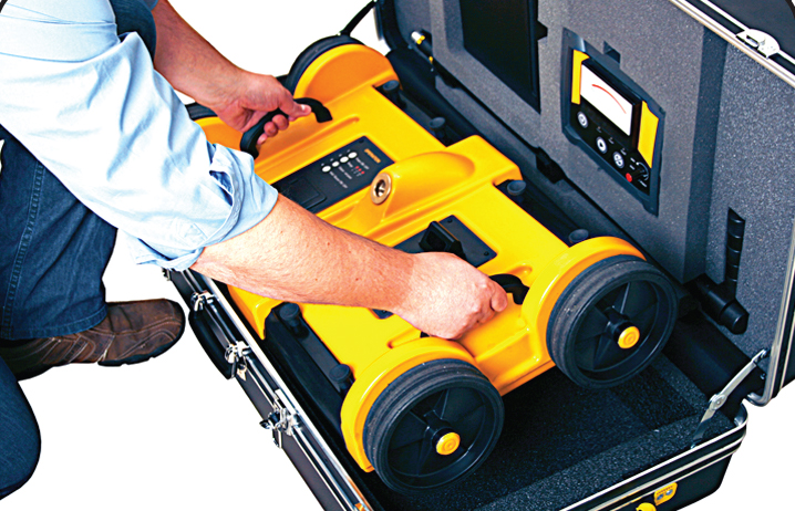
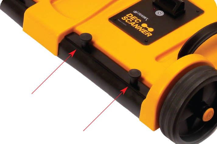
1. Remove the base unit first, lifting with the two black grab handles situated on either side of the body.
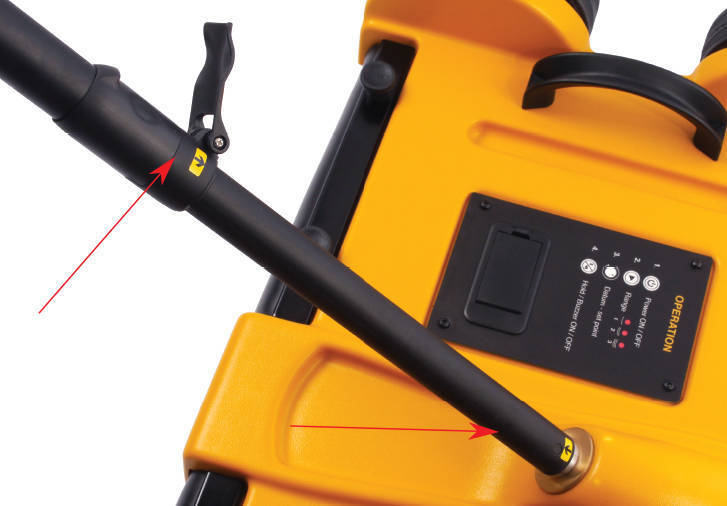
2. Remove the handle and with the locking mechanism fully open on the handle, screw the threaded end into the base until the handle is tight and secure.
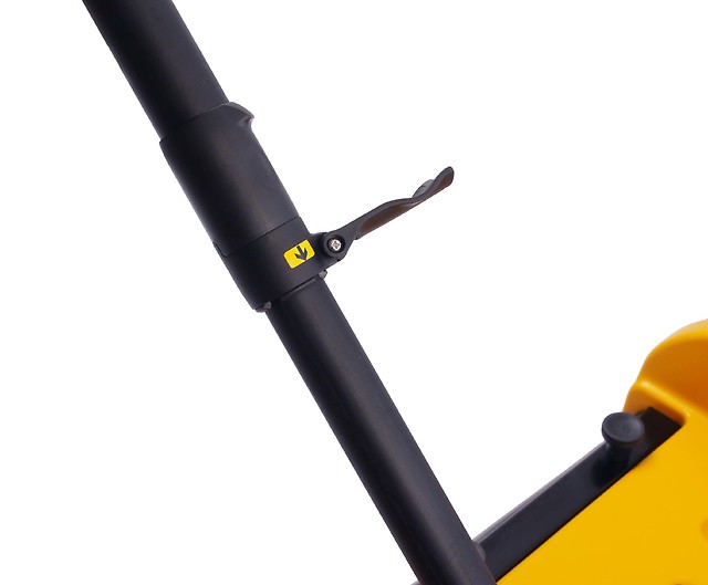
3. Extend the upper part of the handle up to the desired height making sure the arrow label on the mid part of the handle is pointing down to the centre of the base.
4. Then lock the flip-lock, so the upper half of the handle is secure.
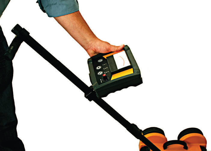
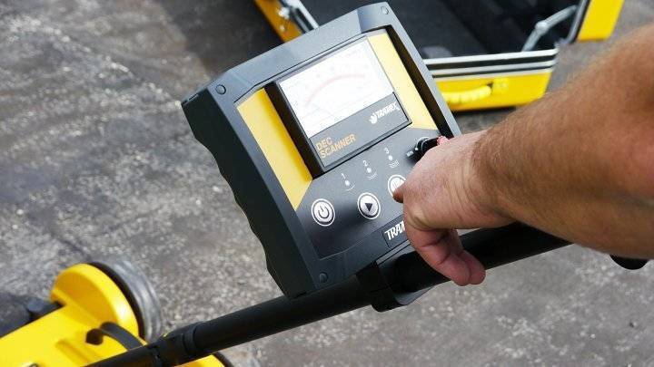
5. Next remove the Control Panel Meter, and mount it to the mounting bracket attached to the upper half of the telescopic handle, by pushing down towards the base unit and making sure it is fully secured and in position.
6. The Dec Scanner can then be maneuvered to the desired position.
7. Always ensure that the electrode mat is completely secured, by making sure the eight grip screws are fully tightened.
Powering on the instrument
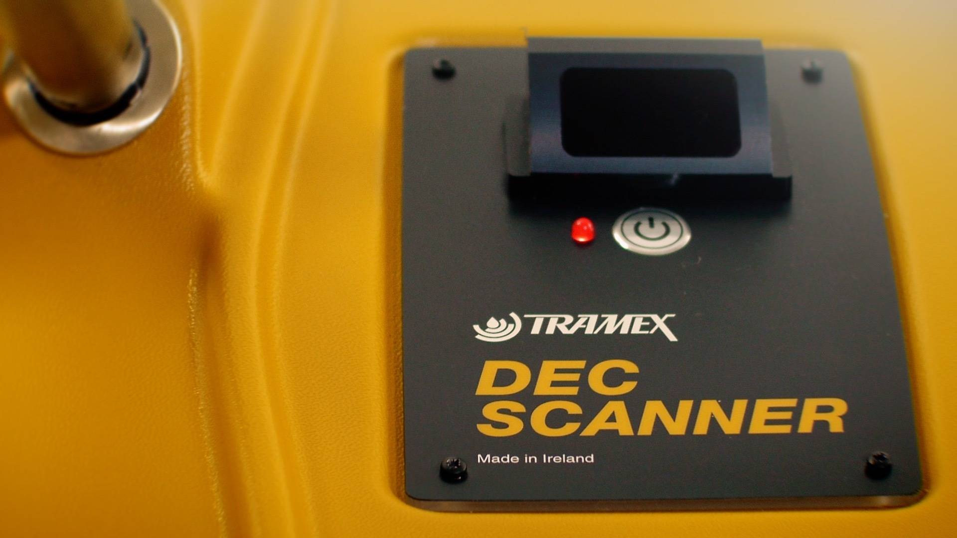
- Now power the unit up by first turning on the base electronics with the on/off button positioned in front of the IR window. The red LED will light solidly to indicate a good battery connection.
- Next power on the control panel with the on/off button, the red LED will also light up on whichever range was selected when the unit was last powered off. The default is set to Range one.
- Then the red LED's will start to flash on both the base and the control panel to indicate a good connection between the two IR links. The unit is now ready to begin testing.
Notes:
- Low Battery Indication: If the base units LED flashes without the head unit being powered on, this indicates the battery needs replacing and this would be the inverse for the head control unit.
- Audio warning signal may be switched on or off by pressing the pause button twice in succession.
Selecting the correct range
The Dec Scanner has 3 ranges of sensitivity:
Range 1: Is most suitable for single ply and thin roof coverings with a maximum depth of signal of up to 30-50mm or 1-2 inches (this Range is the least sensitive)
Range 2: Is most suitable for 3 and 4 ply (BUR) modified systems and mineral surfaced felts with a maximum depth of signal up to 70-80mm or 1-3 inches (this is the middle Range of sensitivity)
Range 3: Is most suitable for thicker roof coverings and thicker layers of insulation, also for gravel and stone surfaced roofing with a maximum depth of 150.0-160.0mm or 1-6 inches (this Range is the most sensitive)
When the unit is powered up and both control panel and base panel are communicating, choose the appropriate Range (as above) with the instrument placed over a known dry area. Adjust the set-point knob, until the needle is just above zero, this will start the signal going into the material under test. If a dry area is not known, position the instrument over a location considered to be dry, adjust the set-point knob until the needle points to mid scale (50). Move the instrument around the roof, following in the direction of lower readings until an area with the lowest readings are found. This should indicate a relative dry area. With the Dec Scanner positioned over this area, adjust the set-point control knob until the needle is just above zero.

Detecting a leak in a flat roof is easy with the Dec Scanner:
- Select the correct range for the type of roof construction in use and adjust the set-point knob until the needle points to mid scale (50).
- Begin in a suspected damp area - such as directly over a leaking area from the ceiling below - and move the instrument around the roof following in the direction of higher readings until full deflection is achieved (100).
- When full deflection is achieved, adjust the set-point knob until the needle points back to mid scale (50) and continue as before.
- Following the highest reading in this way will normally lead to the entry point of the moisture and thus the leak.
- Areas deemed as damp should be confirmed by core sampling using gravimetric analysis in accordance with ASTM C1616. It is permitted to check core samples immediately after extraction with a pin-type resistance meter such as the Tramex PTM or a resistance probe with the CMEX2.
- An identified area of high moisture may also be checked with extended insulated resistance pins before core sampling, by first puncturing the surface of the roofing membrane with the Tramex Hole Punch and then with the Tramex hand held resistance probe – together with 7" or 15" insulated pins – insert the pins into the insulation for a further relative reading.